
TM 5-3805-298-23-4
0389
REMOVAL CONTINUED
NOTE
Follow wire down from switch to locate wiring harness.
Tag and mark wiring harness connectors and note wiring harness routing to aid
installation.
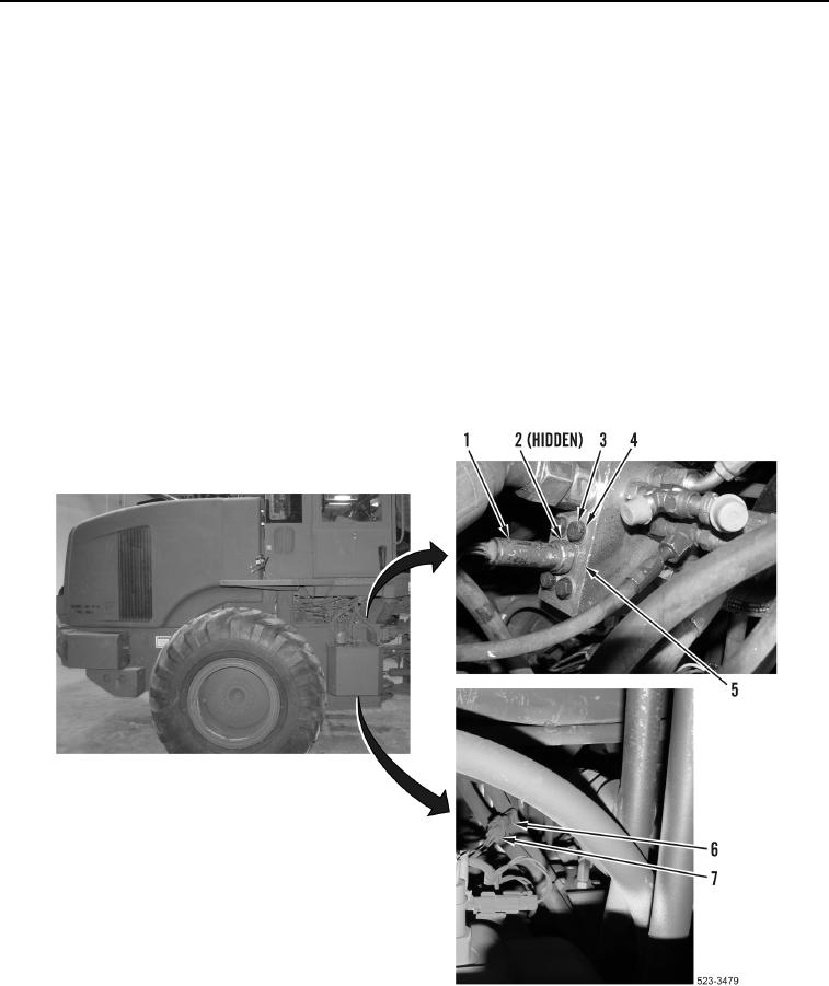
2. Disconnect transmission wiring harness connector (Figure 2, Item 7) from primary steering pressure switch
connector (Figure 2, Item 6).
NOTE
Remove two lower position bolt and one upper position bolt to allow wrench clearance.
3. Remove three bolts (Figure 2, Item 3) and washers (Figure 2, Item 4) from implement pump
(Figure 2, Item 5).
4. Remove primary steering pressure switch (Figure 2, Item 1) from implement pump (Figure 2, Item 5).
5. Remove O-ring (Figure 2, Item 2) from primary steering pressure switch (Figure 2, Item 1). Discard O-ring.
Figure 2. Primary Steering Pressure Switch.
0389
END OF TASK