
TM 5-3805-298-23-4
0390
REMOVAL CONTINUED
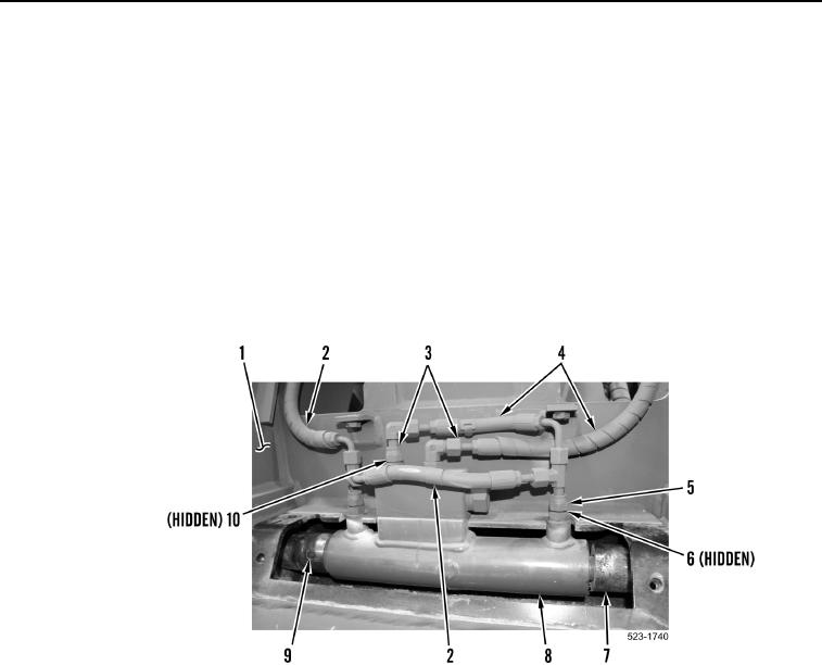
3. Loosen two tube nuts (Figure 2, Item 3), and remove two hoses (Figure 2, Item 4) and O-rings
(Figure 2, Item 10) from quick coupler cylinder (Figure 2, Item 8). Set hoses aside. Discard O-rings.
4. Loosen two tube nuts (Figure 2, Item 5) and remove two hoses (Figure 2, Item 2) and O-rings (Figure 2, Item 6)
from quick coupler cylinder (Figure 2, Item 8). Set hoses aside. Discard O-rings.
NOTE
There is not enough space to drive dowels completely through pins. Dowels will be in back
side of pins when pins are removed.
5. With assistance, drive two dowels (Figure 2, Item 9) from pins (Figure 2, Item 7).
6. With assistance, remove two pins (Figure 2, Item 7), and quick coupler cylinder (Figure 2, Item 8) from quick
coupler assembly (Figure 2, Item 1).
Figure 2. Quick Coupler Cylinder.
0390