
TM 5-3805-298-23-4
0390
INSTALLATION
000390
NOTE
Install fittings as noted during removal.
Install hoses as noted during removal.
Remove caps from hoses and fittings before installation.
1. Install three new O-rings (Figure 3, Item 5) and fittings (Figure 3, Item 4) on quick coupler cylinder (Figure 3,
Item 6).
2. Install new O-ring (Figure 3, Item 3), elbow fitting (Figure 3, Item 1) and jam nut (Figure 3, Item 2) on quick cou-
pler cylinder (Figure 3, Item 6).
3. Install two pins (Figure 4, Item 7) and quick coupler cylinder (Figure 4, Item 8) on quick coupler assembly
(Figure 4, Item 1).
4. With assistance, align dowel holes in pins (Figure 4, Item 7) and quick coupler cylinder (Figure 4, Item 8) and
drive two dowels (Figure 4, Item 9) into pins .
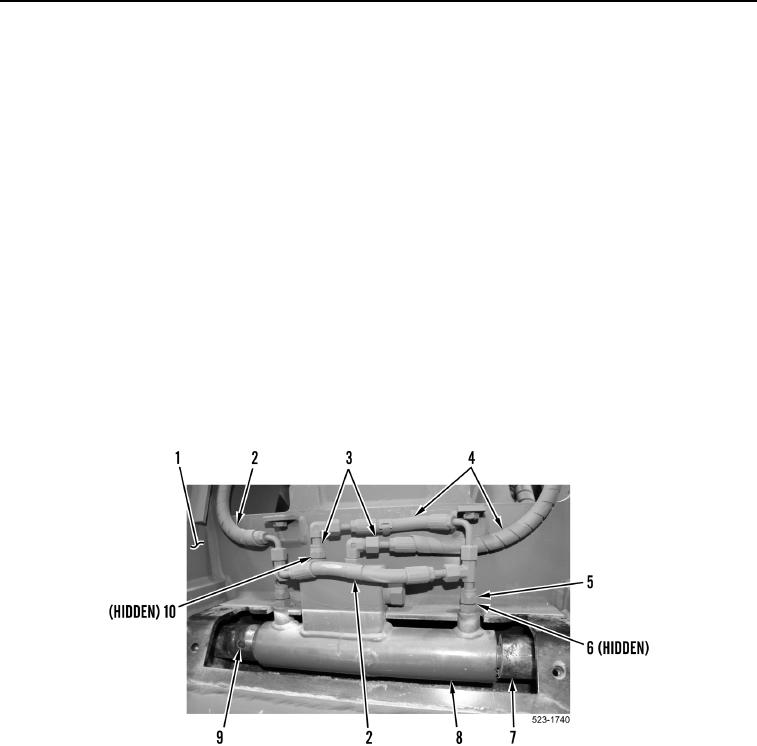
5. Install two new O-rings (Figure 4, Item 10), hoses (Figure 4, Item 2) and tube nuts (Figure 4, Item 5) on quick
coupler cylinder (Figure 4, Item 8).
6. Install two new O-rings (Figure 4, Item 6), hoses (Figure 4, Item 4) and tube nut (Figure 4, Item 3) on quick
coupler cylinder (Figure 4, Item 7).
Figure 4. Quick Coupler Cylinder.
0390