
TM 5-3805-298-23-4
0398
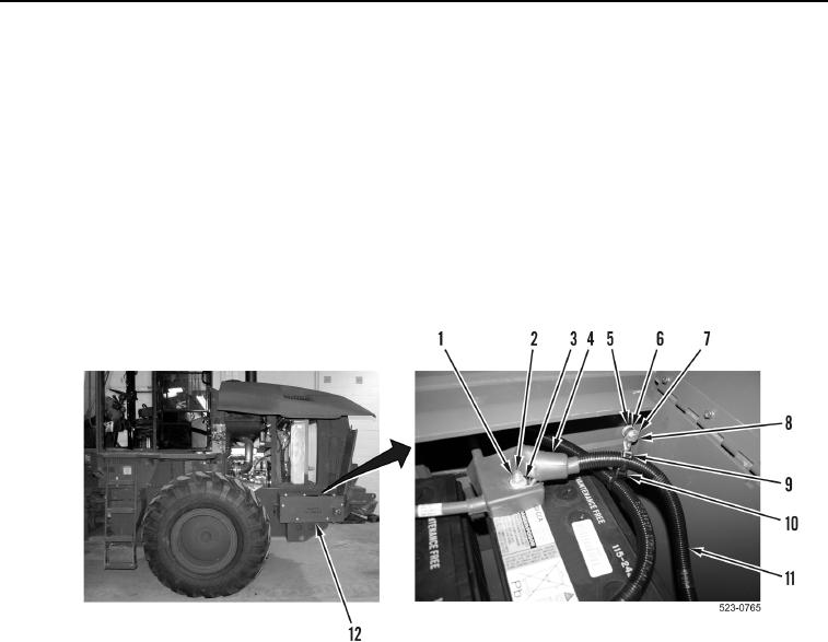
LEFT BATTERIES INSTALLATION CONTINUED
NOTE
Install spacers, washers and cables as noted during removal.
10. Install spacer (Figure 12, Item 6), ground NATO slave cable (Figure 12, Item 8), two washers
(Figure 12, Item 5), and bolt (Figure 12, Item 7), on battery box (Figure 12, Item 12).
11. Install new tiedown strap (Figure 12, Item 9) on saddle (Figure 12, Item 10) and positive NATO slave cable
(Figure 12, Item 11).
12. Install positive NATO slave cable (Figure 12, Item 11), washer (Figure 12, Item 3), and nut (Figure 12, Item 1)
on stud (Figure 12, Item 2).
13. Position positive cable boot (Figure 12, Item 4) over stud (Figure 12, Item 2).
Figure 12. NATO Slave Cables.
0398
END OF TASK