• Home
  • Download PDF
  • Order CD-ROM
  • Order in Print
Figure 16. Left Battery Cable Clamp.
Figure 18. Lower Cooling Assembly Plate.

Field Maintenance Manual For 924H Wheel Loader -4 Page Navigation
  392    393    394    395    396  397  398    399    400    401    402  
img
.
TM 5-3805-298-23-4
0399
INSTALLATION CONTINUED
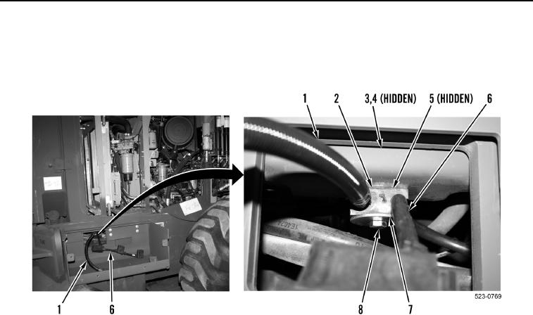
15. Install spacer (Figure 17, Item 5), clamp (Figure 17, Item 2), washer (Figure 17, Item 7), bolt
(Figure 17, Item 8), washer (Figure 17, Item 4), and nut (Figure 17, Item 3) on cable (Figure 17, Item 1) and
cable (Figure 17, Item 6).
Figure 17. Right Battery Cable Clamp.
0399
0399-17


Privacy Statement
Press Release
Contact

© Copyright Integrated Publishing, Inc.. All Rights Reserved.