
TM 5-3805-298-23-4
0403
REMOVAL CONTINUED
NOTE
Tag and mark hoses and note hose routing.
Note location and number of tiedown straps to aid installation.
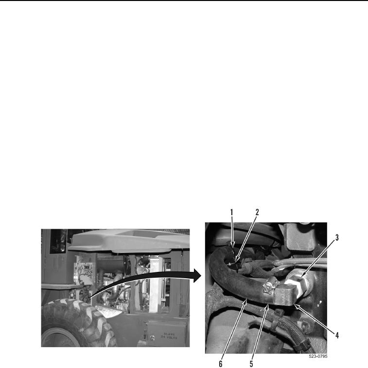
22. Remove tiedown straps (Figure 7, Item 1) from saddles (Figure 7, Item 2) and hose (Figure 7, Item 6). Discard
tiedown straps.
23. Loosen clamp (Figure 7, Item 5) and remove hose (Figure 7, Item 6) from elbow (Figure 7, Item 4). Remove
clamp from hose.
24. Remove hose (Figure 7, Item 6) from machine.
NOTE
If elbow and fittings are damaged or a leak is present, perform steps 25 and 26.
If removal is necessary, note position of elbow and fitting to aid installation.
25. Remove elbow (Figure 7, Item 4) and fitting (Figure 7, Item 3) from engine.
26. Remove elbow (Figure 7, Item 4) from fitting (Figure 7, Item 3).
Figure 7. Elbow.
0403
END OF TASK
CLEANING AND INSPECTION
000403
Clean and inspect all parts IAW Mechanical General Maintenance Instructions (WP 0172).
END OF TASK