
TM 5-3805-298-23-4
0403
INSTALLATION CONTINUED
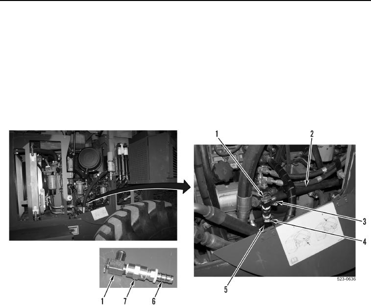
14. Apply sealing compound to threads of fitting (Figure 11, Item 6) and valve (Figure 11, Item 1).
15. Install valve (Figure 11, Item 1) and fitting (Figure 11, Item 6) on adapter (Figure 11, Item 7).
16. Position valve (Figure 11, Item 1) on machine.
NOTE
Route hoses and install clamps as noted during removal.
17. Install hose (Figure 11, Item 5) and clamp (Figure 11, Item 4) on valve (Figure 11, Item 1)
18. Install hose (Figure 11, Item 2) and clamp (Figure 11, Item 3) on valve (Figure 11, Item 1).
Figure 11. Valve Assembly.
0403