
TM 5-3805-298-23-4
0403
INSTALLATION
000403
NOTE
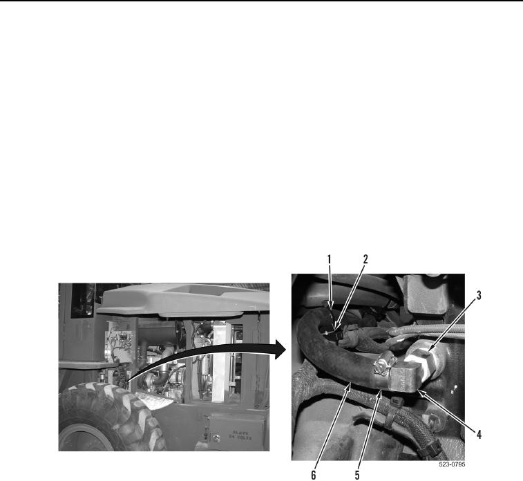
Install elbow and fitting as noted during removal.
1. Apply sealing compound to threads of fitting (Figure 8, Item 3) and elbow (Figure 8, Item 4).
2. Install elbow (Figure 8, Item 4) on fitting (Figure 8, Item 3).
3. Install fitting (Figure 8, Item 3) and elbow (Figure 8, Item 4) on engine.
NOTE
Route hoses and install tiedown straps as noted during removal.
4. Position hose (Figure 8, Item 6) on machine.
5. Install hose (Figure 8, Item 6) and clamp (Figure 8, Item 5) on elbow (Figure 8, Item 4).
6. Install new tiedown straps (Figure 8, Item 1) on hose (Figure 8, Item 6) and saddles (Figure 8, Item 2).
Figure 8. Elbow.
0403