
TM 5-3805-298-23-4
0406
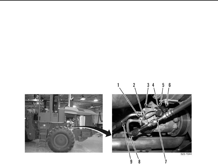
A/C COMPRESSOR REMOVAL CONTINUED
5. Remove bolt (Figure 2, Item 1) and plate (Figure 2, Item 2) from A/C compressor (Figure 2, Item 3).
6. Remove A/C lines (Figure 2, Items 8 and 9) from A/C compressor (Figure 2, Item 3) and position aside.
NOTE
Tag and mark all wiring harness connectors and note wiring harness routing to aid
installation.
7. Remove tiedown strap (Figure 2, Item 5) from engine control wiring harness connector (Figure 2, Item 6) and
clip (Figure 2, Item 7). Discard tiedown strap.
8. Disconnect engine wiring harness (Figure 2, Item 6) from wiring harness connector (Figure 2, Item 4).
Figure 2. A/C Lines, Tiedown Strap, and Connector.
0406