
TM 5-3805-298-23-4
0405
A/C SYSTEM PERFORMANCE TEST CONTINUED
000405
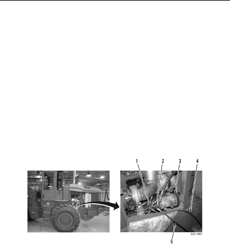
1. Install blue low-side hose (Figure 4, Item 4) on suction (low) side (Figure 4, Item 1) of A/C compressor
(Figure 3, Item 3).
2. Install red high-side hose (Figure 4, Item 5) on discharge (high) side (Figure 4, Item 2) of A/C compressor
(Figure 4, Item 3).
CAUTION
DO NOT invert R-134a refrigerant tank while charging A/C system. Liquid refrigerant
entering low side of A/C system will permanently damage compressor.
3. Start and run engine at 1,000 rpm (low idle) (TM 5-3805-298-10).
4. Set cab temperature control knob to MAXIMUM cool position (TM 5-3805-298-10).
5. Turn air conditioning ON (TM 5-3805-298-10).
6. Set cab fan speed switch on HIGH position (TM 5-3805-298-10).
7. After 10 to 15 minutes of operation, adjust engine idle speed to approximately 1,300 to 1,400 rpm (TM 5-3805-
298-10).
8. From recovery station, record discharge (high side) pressure gauge reading and suction (low side) pressure
gauge reading.
9. Compare discharge (high side) pressure gauge reading and suction (low side) pressure gauge reading to
pressures listed in Table 1, Pressure Range Table to determine if system is functioning correctly at current
ambient temperature.
10. Refer to troubleshooting if A/C pressures are not within pressure listed in Table 1.
Figure 4. Charging Station Hook-Up.
0405