
TM 5-2420-231-10
0008
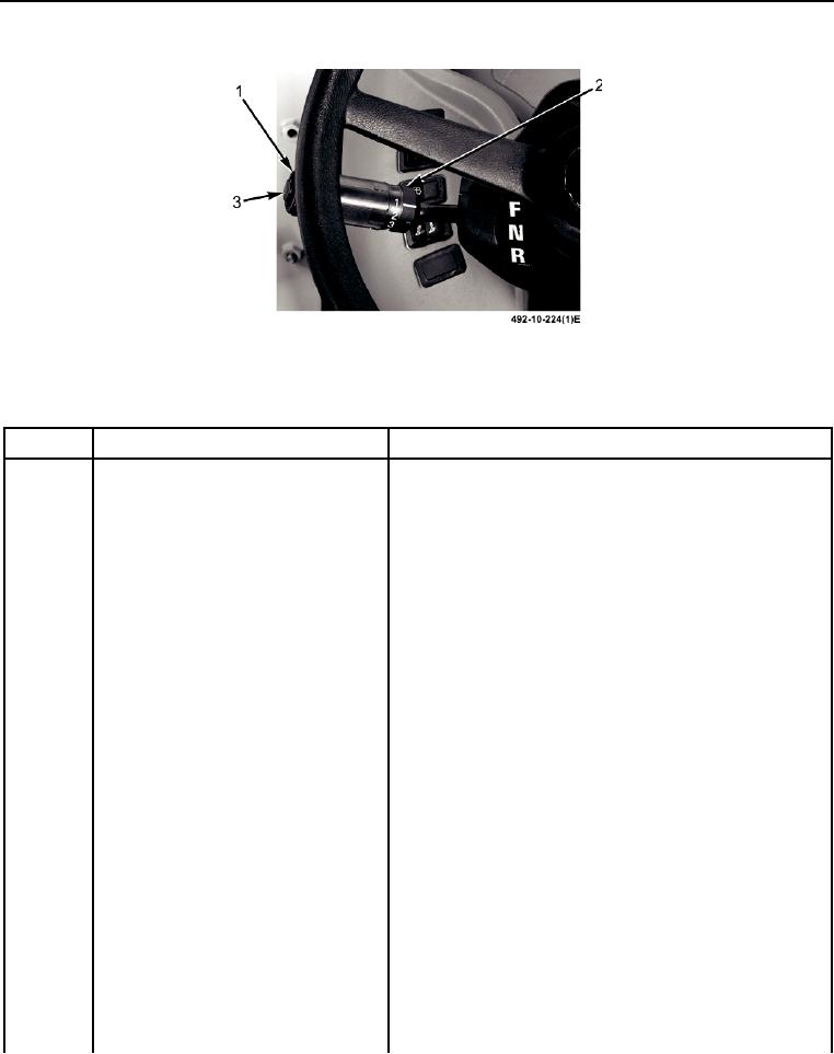
TRANSMISSION
Figure 1. Transmission Controls/Indicators (Sheet 1 of 2).
Table 1. Transmission Controls/Indicators.
KEY
CONTROL/INDICATOR
FUNCTION
1
Direction control lever
Lever controls travel direction of the BHL. Center position
N is neutral. To travel forward in 1st, 2nd, 3rd, or 4th
gear, lift lever and push all the way forward toward
F position. To travel in reverse in 1st or 2nd gear, lift
lever and pull completely rearward toward R position.
2
Gear selection control lever
Used to select gears (1, 2, 3, 4). Rotate lever handgrip to
aline number, which corresponds to each gear, with
indicator mark on lever.
Manual transmission mode
The BHL will stay in selected gear until selection is
changed. Gear change can be made without stopping the
BHL.
Position 1
1st gear (forward or reverse).
Position 2
2nd gear (forward or reverse).
Position 3
3rd gear (forward only).
Position 4
4th gear (forward only).
Automatic transmission mode
The BHL will reach maximum gear selected by gear
selection control lever.
Position 1
No automatic shifting; transmission will remain in 1st
gear.
Position 2
No automatic shifting; transmission will remain in 2nd
gear.
Position 3
Automatic shifting between 2nd and 3rd gears.
Position 4
Automatic shifting between 2nd, 3rd, and 4th gears.