
TM 5-2420-231-10
0008
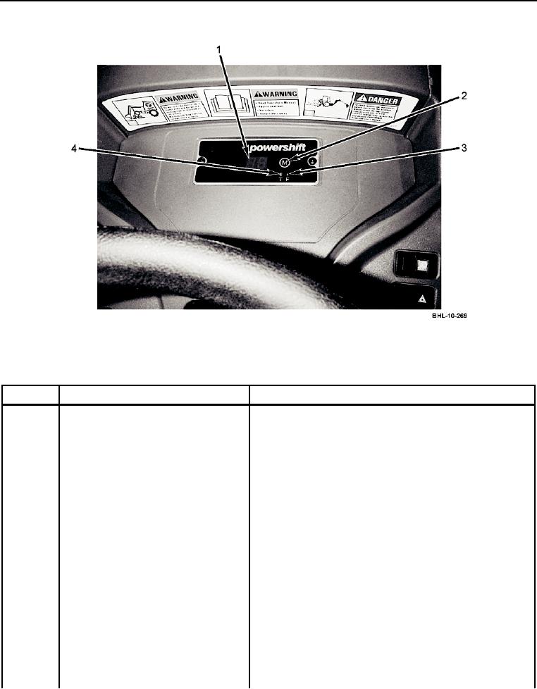
DISPLAY SCREEN
Figure 2. Display Screen Controls/Indicators (Sheet 1 of 4).
Table 2. Display Screen Controls/Indicators.
KEY
CONTROL/INDICATOR
FUNCTION
1
Display screen
Displays GA momentarily upon startup to indicate self
test. Displays direction control lever position (F, N, R),
gear selection control lever position (1, 2, 3, 4), and
vehicle speed (km/h). (Below 10 km/h, speed is displayed
with 0.1 km/h resolution.)
2
Mode selection button M
Used to select mode displayed on display screen. Press
and release button until desired mode is displayed on
display screen.
3
Indicator lamp F
Illuminates momentarily upon startup as module goes
(reset mode indicator lamp)
through self-test.
CAUTION
If indicator lamp T blinks, Sd will be displayed on
display screen. Move to safe location, shut engine
off, and notify field level maintenance. Failure to
comply may result in damage to transmission.
4
Indicator lamp T
Blinks to indicate failure in transmission electrical circuit.
(test mode and fault indicator lamp)
Press and hold mode selection button M until failure code
is displayed. (Failure code is to be provided to field level
maintenance personnel.)