
TM 5-2420-231-23-1
0018
Table 1. Instrument Cluster Does Not Function - Continued.
018
MALFUNCTION
TEST OR INSPECTION
CORRECTIVE ACTION
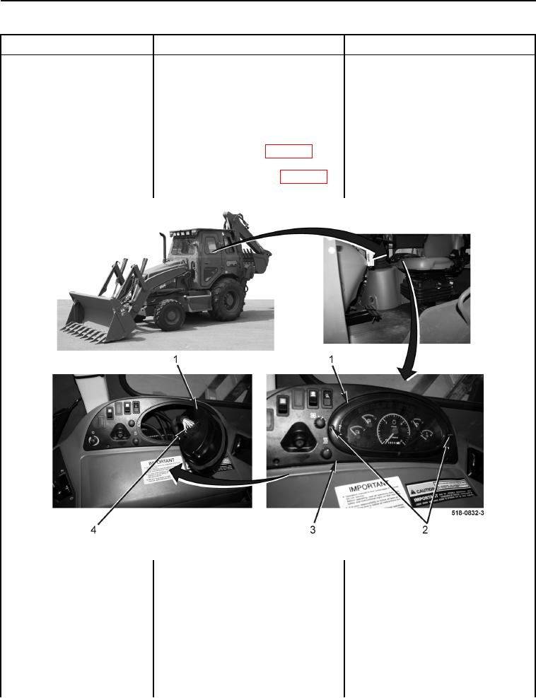
5. Remove two screws (Figure 3,
Instrument Cluster Does Not
Item 2) from instrument panel clus-
Function - Continued
ter (Figure 3, Item 1), pull instru-
ment panel cluster (Figure 3,
Item 1) from bezel (Figure 3,
Item 3), and disconnect side con-
sole wiring harness connector
(Figure 3, Item 4) (WP 0007, Fig-
ure 28) from instrument panel clus-
ter (Figure 3, Item 1) (WP 0007,
Figure 29).
Figure 3. Instrument Cluster.
0018
6. Install new instrument alarm fuse
(TM 5-2420-231-10).
7. Connect batteries (WP 0157) and
turn ignition switch into the on
position (TM 5-2420-231-10).
8. Inspect instrument alarm fuse (TM
Instrument Alarm Fuse OK - Replace
5-2420-231-10).
instrument cluster (WP 0177).
Proceed to Test Step 4.
Instrument Alarm Fuse Open -
Proceed to step 9.