
TM 5-2420-231-23-1
0018
Table 1. Instrument Cluster Does Not Function - Continued.
018
MALFUNCTION
TEST OR INSPECTION
CORRECTIVE ACTION
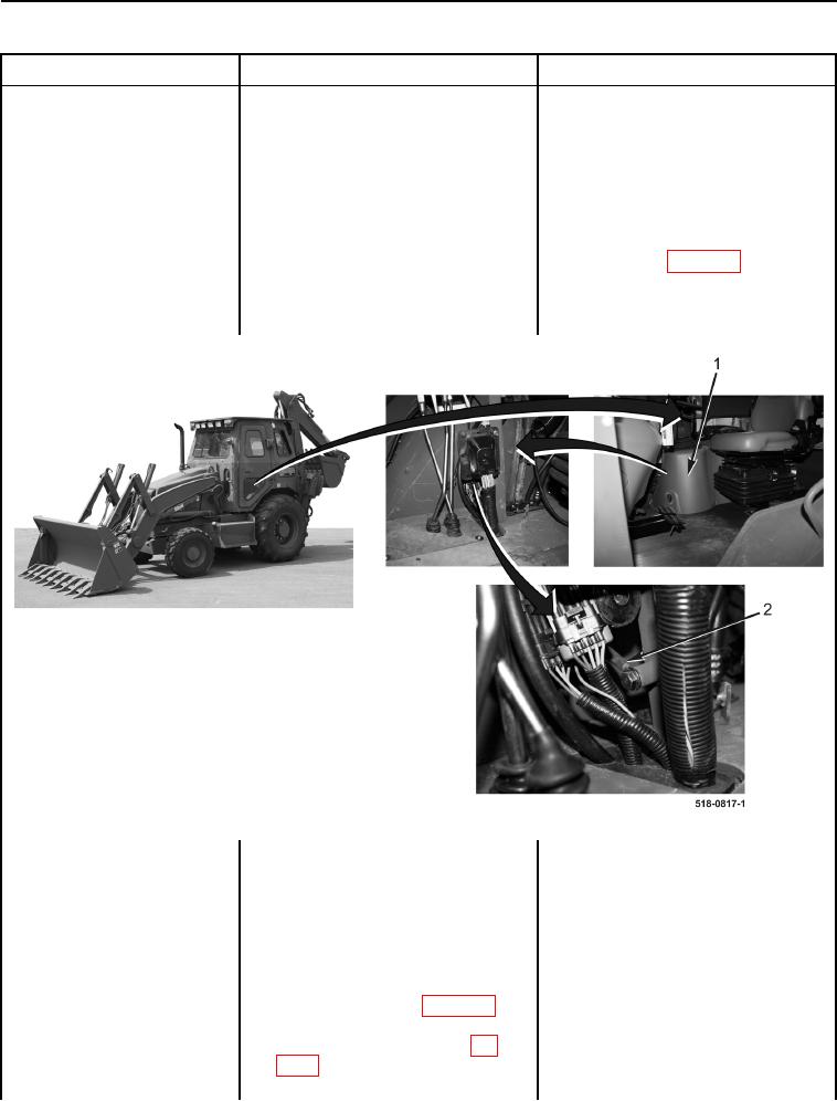
7. Remove front instrument panel
Instrument Cluster Does Not
right-side cover (Figure 5, Item 1)
Function - Continued
(WP 0176).
8. Inspect side console ground
Side Console Ground OK - Replace
(Figure 5, Item 2) for being clean
side console wiring harness (WP 0170).
and tight.
Proceed to Test Step 4.
Side Console Ground Loose or
Corroded - Clean and tighten side
console ground (WP 0007, Figure 31).
If ground is OK, replace side console
wiring harness (WP 0170).
Proceed to Test Step 4.
Figure 5. Instrument Panel Right-Side Cover and Side Console Ground.
0018
Test Step 3. Test Instrument Cluster
Voltage Supply Circuit.
1. Turn ignition switch to the off posi-
tion (TM 5-2420-231-10).
2. Remove front instrument panel
right-side cover (WP 0176).
3. Disconnect side console wiring
harness connector (WP 0007,
Figure 24) from rear main chassis
wiring harness connector (WP
0007, Figure 25).