
TM 5-2420-231-23-1
0085
CHECKING FUEL INJECTION PUMP TIMING CONTINUED
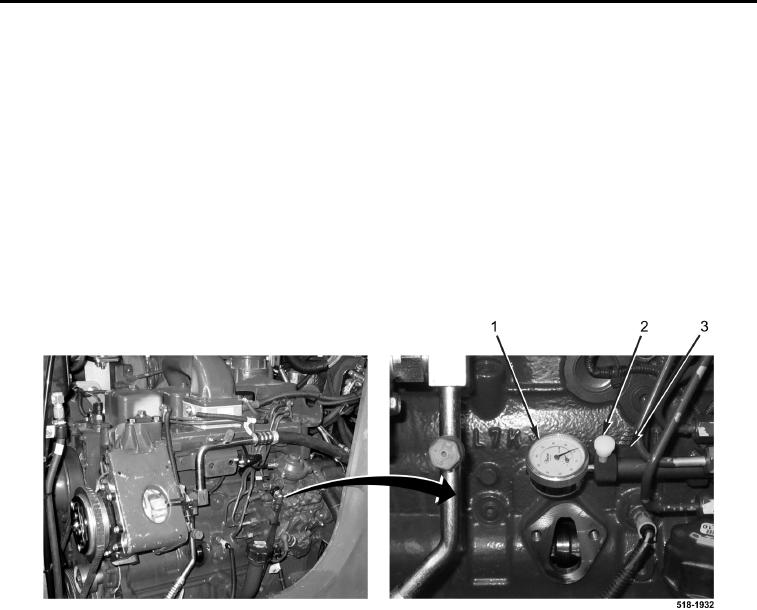
9. Install dial indicator (Figure 15, Item 1) on injector pump timing tool (Figure 15, Item 3) until needle sweeps dial
2-1/2 times.
10. Tighten retaining screw (Figure 15, Item 2) on injector pump timing tool (Figure 15, Item 3) to secure dial
indicator (Figure 15, Item 1) in position.
11. Remove timing pin tool from timing pin housing.
12. Rotate engine counterclockwise until dial indicator (Figure 15, Item 1) stops moving.
13. Zero dial indicator (Figure 15, Item 1).
14. Rotate engine clockwise to TDC and fully install timing pin (Figure 12, Item 1) in drive gear (Figure 12, Item 2).
Dial indicator (Figure 15, Item 1) should read 1 to 1.1 mm (0.039 to 0.043 in.).
a. Less than 1 mm (0.039 in.): pump timing is retarded.
b. Greater than 1.10 mm (0.043 in.): pump timing is advanced.
Figure 15. Dial Indicator.
0085