
34
TM 5-2420-231-23-2
FIELD MAINTENANCE
-
ENGINE REPLACEMENT
00
91
Removal, Preparation for Shipment, Cleaning and Inspection,
Preparation for Installation, Installation
INITIAL SETUP
Tools and Special Tools
Materials/Parts - Continued
Tool Kit, General Mechanic's
O-ring (2)
0
0
(WP 0376, Item 117)
Personnel Required
Bracket, Vehicular (Engine Mounting)
Three
0
0
(WP 0376, Item 7)
References
Chain, Chain Hoist, 9/32", Wll 3,500-lb, L 11-1/
0
TM 5-2420-231-10
2" SGG (WP 0376, Item 11)
0
WP 0085
Rotation Tool, Engine (WP 0376, Item 75)
0
0
WP 0369
Lifting Device (1,500-lb capacity)
0
0
WP 0370
Suitable Engine Stand
0
0
WP 0374 (Group Number 0107, 0201, and
Materials/Parts
0
0508)
Cap Set, Protective, Dust and Moisture
0
Equipment Conditions
(WP 0375, Item 4)
Coolant pack removed (WP 0092)
Oil, Engine, 15W40 (WP 0375, Item 22)
0
0
Air cleaner assembly removed (WP 0100)
Rag, Wiping (WP 0375, Item 25)
0
0
Starter removed (WP 0152)
Tape, Antiseizing Teflon (WP 0375, Item 34)
0
0
Engine oil drained (WP 0126)
Tiedown Strap (WP 0375, Item 35)
0
0
Alternator removed (WP 0153)
Gasket (4)
0
0
Estimated Time to Complete
Locknut (3)
0
Lockwasher (2)
20.0 hr
0
0
REMOVAL
0091
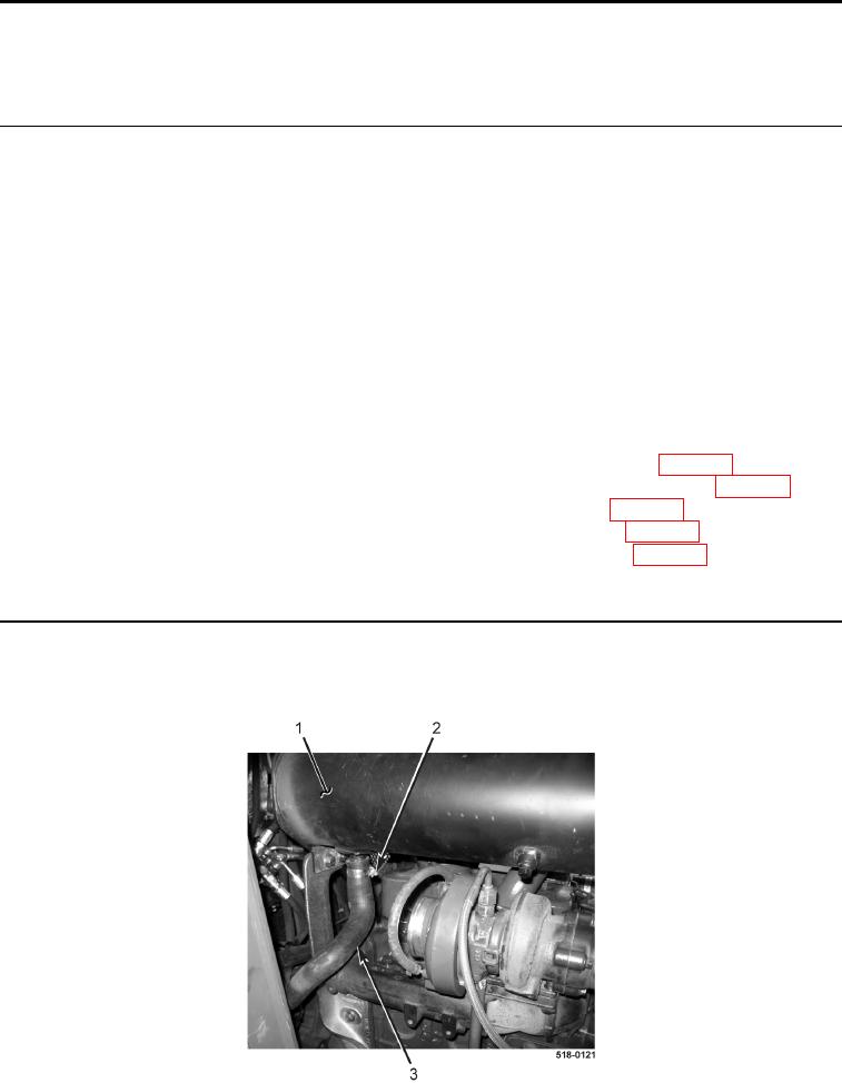
1. Loosen clamp (Figure 1, Item 2) and disconnect aspirate check valve hose (Figure 1, Item 3) from muffler
(Figure 1, Item 1).
2. Remove aspirate check valve hose (Figure 1, Item 3) from machine.
Figure 1. Aspirate Check Valve Hose.
0091