
TM 5-2420-231-23-2
0091
REMOVAL CONTINUED
NOTE
Tag and mark wires to aid in installation.
Note routing of wires to aid in installation.
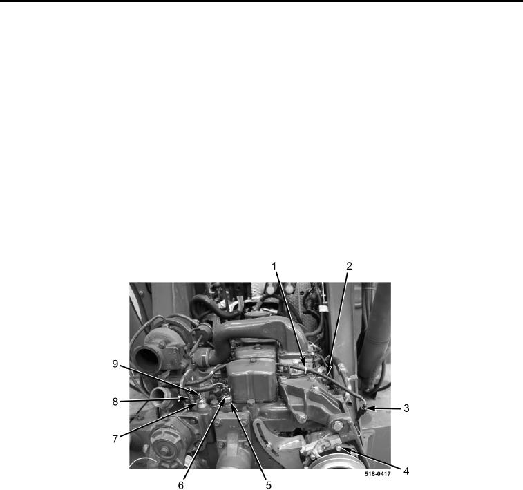
11. Remove locknut (Figure 5, Item 9) and wire (Figure 5, Item 8) from coolant temperature sender (Figure 5,
Item 7). Discard locknut.
12. Disconnect connector (Figure 5, Item 6) from coolant temperature sensor (Figure 5, Item 5).
NOTE
Note location and quantity of tiedown straps to aid in installation.
13. Remove tiedown straps (Figure 5, Item 1) from wiring harness (Figure 5, Item 2). Discard tiedown straps.
14. Disconnect connector (Figure 5, Item 3) from A/C compressor (Figure 5, Item 4).
15. Position wiring harnesses aside.
Figure 5. Wiring Harness.
0091