
TM 5-2420-231-23-2
0130
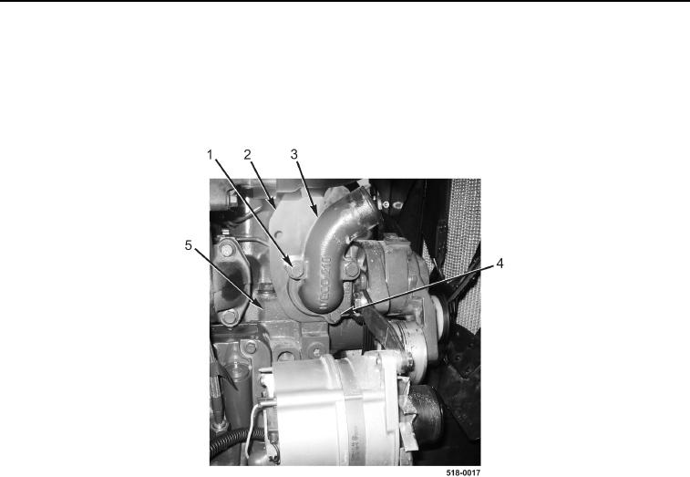
INSTALLATION CONTINUED
2. Install engine lift eye (Figure 6, Item 2), thermostat housing (Figure 6, Item 3), and bolt (Figure 6, Item 4) on
cylinder head (Figure 6, Item 5). Do not tighten bolt at this time.
3. Install two bolts (Figure 6, Item 1) on thermostat housing (Figure 6, Item 3). Do not tighten bolts at this time.
4. Tighten bolts (Figure 6, Items 1 and 4) to 21 lb-ft (28 Nm).
Figure 6. Thermostat Housing.
0130