
TM 5-2420-231-23-2
0130
INSTALLATION CONTINUED
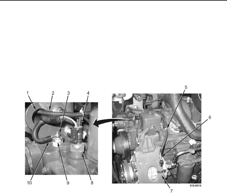
6. Feed wiring harness (Figure 8, Item 2) through engine lift bracket (Figure 8, Item 1).
7. Install eyelet (Figure 8, Item 10) and new locknut (Figure 8, Item 3) on coolant temperature sensor
(Figure 8, Item 9).
8. Connect wiring harness connector (Figure 8, Item 4) to coolant temperature switch (Figure 8, Item 8).
9. Connect wiring harness connector (Figure 8, Item 6) to A/C compressor pigtail connector (Figure 8, Item 7).
NOTE
Install tiedown straps in location and quantity as noted during removal.
10. Install new tiedown straps (Figure 8, Item 5) on wiring harness (Figure 8, Item 2).
Figure 8. Sensor Connections.
0130