
TM 5-2420-231-23-2
0130
REMOVAL CONTINUED
NOTE
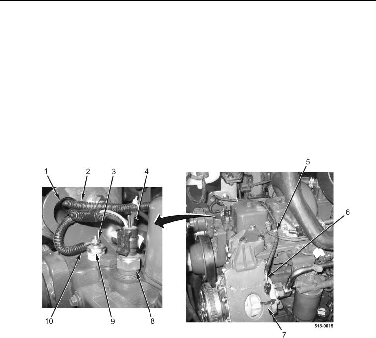
Note location and number of tiedown straps to aid in installation.
2. Remove tiedown straps (Figure 2, Item 5) from wiring harness (Figure 2, Item 2). Discard tiedown straps.
3. Disconnect wiring harness connector (Figure 2, Item 6) from A/C compressor pigtail connector
(Figure 2, Item 7).
4. Disconnect wiring harness connector (Figure 2, Item 4) from coolant temperature switch (Figure 2, Item 8).
5. Remove locknut (Figure 2, Item 3) and eyelet (Figure 2, Item 10) from coolant temperature sensor (Figure 2,
Item 9). Discard locknut.
6. Feed wiring harness (Figure 2, Item 2) through engine lift bracket (Figure 2, Item 1). Position wiring harness
aside.
Figure 2. Sensor Connections.
0130