
TM 5-2420-231-23-2
0130
REMOVAL CONTINUED
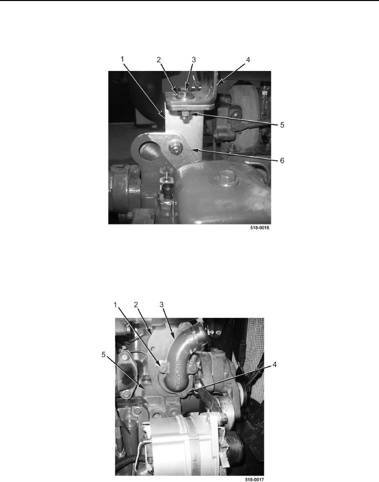
7. Remove four bolts (Figure 3, Item 3), nuts (Figure 3, Item 5), eight washers (Figure 3, Item 2), and bracket
(Figure 3, Item 1) from engine lift eye (Figure 3, Item 6) and exhaust bracket (Figure 3, Item 4).
Figure 3. Exhaust Bracket.
0130
8. Remove two bolts (Figure 4, Item 1) from thermostat housing (Figure 4, Item 3).
9. Remove bolt (Figure 4, Item 4), thermostat housing (Figure 4, Item 3), and engine lift eye (Figure 4, Item 2)
from cylinder head (Figure 4, Item 5).
Figure 4. Thermostat Housing.
0130