
TM 5-2420-231-23-2
0142
INSTALLATION
0142
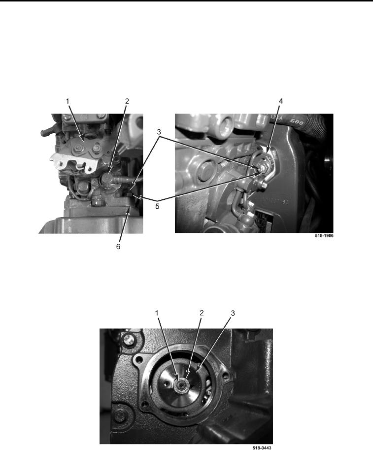
1. Install new gasket (Figure 13, Item 6), high-pressure fuel pump (Figure 13, Item 1), and three nuts (Figure 13,
Item 5) on engine.
2. Studs (Figure 13, Item 3) should be located in center of elongated hole (Figure 13, Item 4) to allow for pump
adjustment.
3. Tighten three nuts (Figure 13, Item 5).
4. Connect fuel line (Figure 13, Item 2) to high-pressure fuel pump (Figure 13, Item 1).
Figure 13. High-Pressure Fuel Pump.
0142
5. Install new lockwasher (Figure 14, Item 2) and nut (Figure 13, Item 1) on high-pressure fuel pump gear
(Figure 13, Item 3). Tighten nut to 70 lb-ft (95 Nm).
Figure 14. High-Pressure Fuel Pump Gear.
0142