
TM 5-2420-231-23-2
0142
INSTALLATION CONTINUED
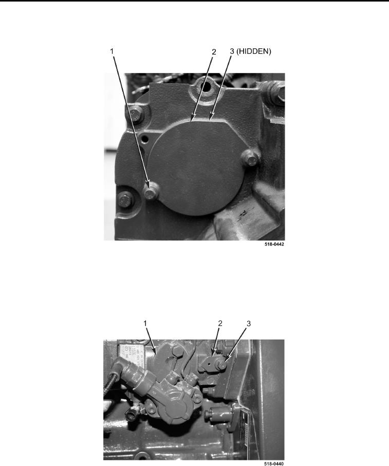
6. Install plate (Figure 15, Item 2), new O-ring (Figure 15, Item 3), and two bolts (Figure 15, Item 1) on engine.
Figure 15. Plate.
0142
7. Loosen locking bolt (Figure 16, Item 3) on high-pressure fuel pump (Figure 16, Item 1).
8. Install spacer (Figure 16, Item 2) and tighten locking bolt (Figure 16, Item 3) on high-pressure fuel pump
(Figure 16, Item 1).
Figure 16. High-Pressure Fuel Pump Locking Bolt.
0142