
2
TM 5-2420-231-23-2
FIELD MAINTENANCE
-
COLD START TEMPERATURE SWITCH REPLACEMENT
0143
Removal, Cleaning and Inspection, Installation
INITIAL SETUP
References - Continued
Tools and Special Tools
Tool Kit, General Mechanic's
WP 0370
0
0
(WP 0376, Item 117)
WP 0374 (Group Number 0204)
0
Socket, Deep Well, 12 Pt, 1", 1/2" Dr.
0
Equipment Conditions
(WP 0376, Item 88)
Engine hood raised (TM 5-2420-231-10)
0
Materials/Parts
Front end loader raised with safety support
0
Rag, Wiping (WP 0375, Item 25)
strut engaged (TM 5-2420-231-10)
0
Tape, Antiseizing Teflon (WP 0375, Item 34)
Engine coolant drained (WP 0090)
0
0
Tiedown Strap (WP 0375, Item 35)
0
Estimated Time to Complete
References
1.6 hr
0
WP 0369
0
REMOVAL
0143
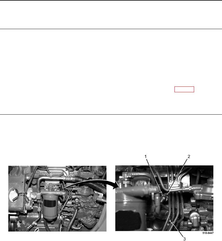
1. Remove tiedown strap (Figure 1, Item 3) and disconnect wiring harness connector (Figure 1, Item 1) from cold
start temperature switch (Figure 1, Item 2). Discard tiedown strap.
2. Remove cold start temperature switch (Figure 1, Item 2) from engine.
Figure 1. Cold Start Temperature Switch.
0143
END OF TASK