
TM 5-2420-231-23-2
0158
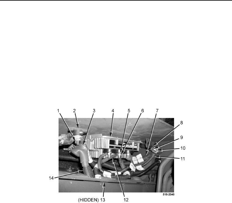
INSTALLATION CONTINUED
1. Push ground cable (Figure 6, Item 7) through grommet hole (Figure 6, Item 13) and route to stud
(Figure 6, Item 9).
2. Connect three ground cables (Figure 6, Items 7, 8, and 11) and install nut (Figure 6, Item 10) on stud
(Figure 6, Item 9).
3. Push 12-V battery cable (Figure 6, Item 12) through grommet hole (Figure 6, Item 13) and route to equalizer
(Figure 6, Item 4).
4. Connect 12-V battery cable (Figure 6, Item 12) to equalizer (Figure 6, Item 4) and install new lockwasher
(Figure 6, Item 5) and nut (Figure 6, Item 6).
5. Push 24-V battery cable (Figure 6, Item 14) through grommet hole (Figure 6, Item 13) and route to junction
block (Figure 6, Item 2).
6. Connect 24-V battery cable (Figure 6, Item 14) and install nut (Figure 6, Item 1) on junction block
(Figure 6, Item 2).
7. Position rubber boot (Figure 6, Item 3) on junction block (Figure 6, Item 2).
Figure 6. Equalizer.
0158