
TM 5-2420-231-23-2
0159
INSTALLATION
0159
NOTE
Install wires as tagged and marked during removal.
1. With assistance, push cable (Figure 12, Item 6) through grommet hole (Figure 12, Item 1) and position cable
on machine.
2. Connect four 24-V cables (Figure 12, Items 3, 5, 6, and 8) and install nut (Figure 12, Item 4) on junction block
(Figure 12, Item 7).
3. Position rubber boot (Figure 12, Item 2) on terminals.
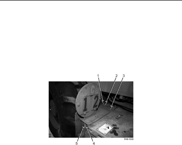
4. Install equalizer cover (Figure 13, Item 3), washer (Figure 13, Item 4), and bolt (Figure 13, Item 5) on machine.
5. Install two washers (Figure 13, Item 2) and bolts (Figure 13, Item 1) on equalizer cover (Figure 13, Item 3).
Figure 13. Equalizer Cover.
0159