
TM 5-2420-231-23-2
0159
INSTALLATION CONTINUED
NOTE
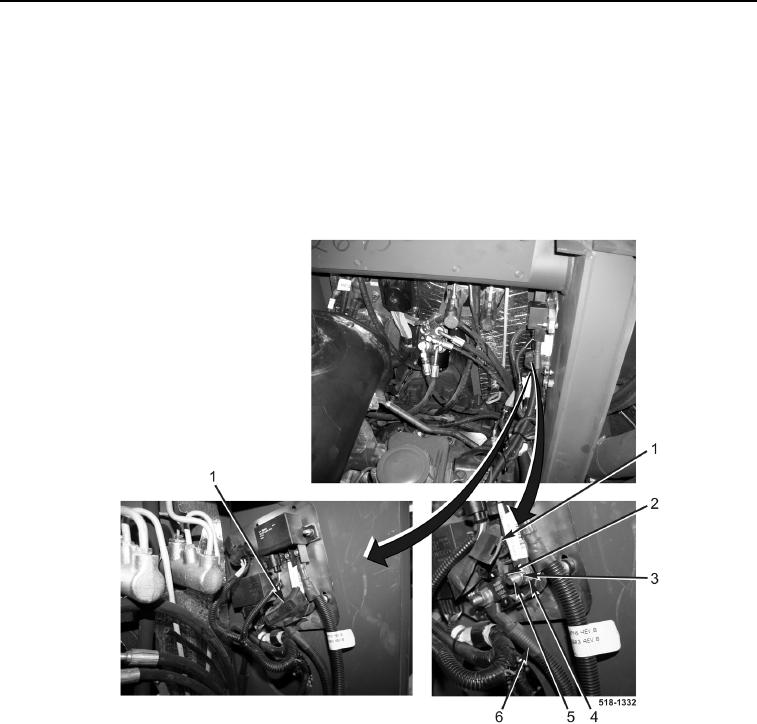
Install wires as tagged and marked during removal.
9. Connect cable (Figure 16, Item 6) to stud (Figure 16, Item 5).
10. Install fuse (Figure 16, Item 2), two new lockwashers (Figure 16, Item 4), and nuts (Figure 16, Item 3) on two
studs (Figure 16, Item 5).
11. Position rubber boot (Figure 16, Item 1) over terminals.
Figure 16. Grid Heater Fuse.
0159