
4
TM 5-2420-231-23-2
FIELD MAINTENANCE
-
POWERSHIFT LEVER REPLACEMENT
0165
Removal, Cleaning and Inspection, Installation
INITIAL SETUP
References - Continued
Tools and Special Tools
Tool Kit, General Mechanic's
WP 0374 (Group Number 0306)
0
0
(WP 0376, Item 117)
Equipment Conditions
Materials/Parts
Steering wheel removed (WP 0199)
0
Rag, Wiping (WP 0375, Item 25)
Batteries disconnected (WP 0157)
0
0
References
Estimated Time to Complete
WP 0369
0.5 hr
0
0
WP 0370
0
REMOVAL
0165
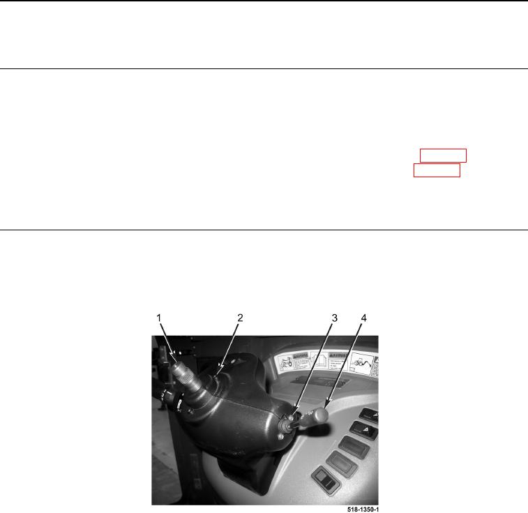
1. Remove two screws (Figure 1, Item 2) from steering column (Figure 1, Item 1).
2. Remove two screws (Figure 1, Item 3) from turn signal switch (Figure 1, Item 4).
Figure 1. Steering Column and Turn Signal Switch.
0165