
TM 5-2420-231-23-2
0165
CLEANING AND INSPECTION
0165
1. Clean and inspect all parts IAW Mechanical General Maintenance Instructions (WP 0369).
2. Clean and inspect all parts IAW Electrical General Maintenance Instructions (WP 0370).
END OF TASK
INSTALLATION
0165
NOTE
Install wires as tagged and marked during removal.
1. Install powershift lever (Figure 3, Item 2) and two screws (Figure 3, Item 3) on machine.
2. Connect front console wiring harness (Figure 3, Item 1) to powershift lever (Figure 3, Item 2).
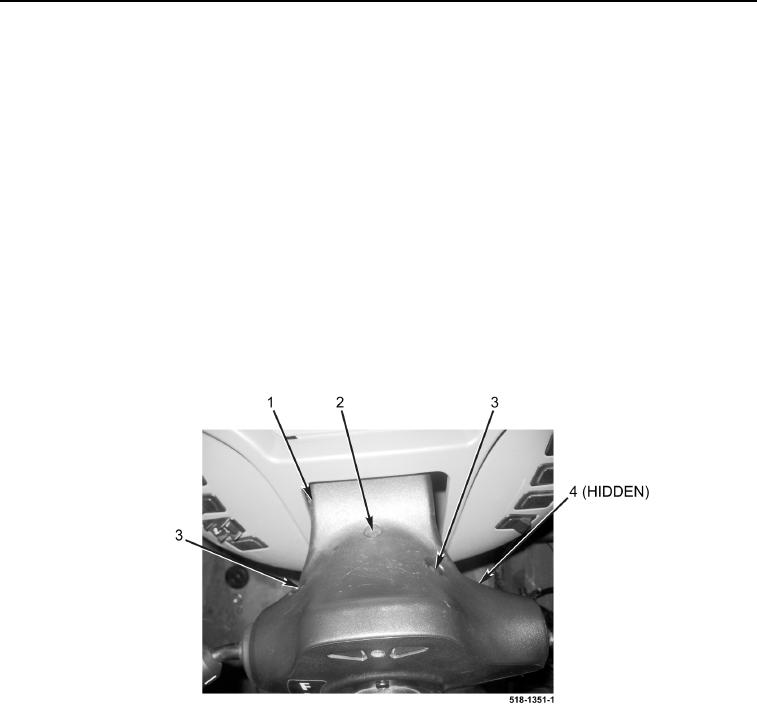
3. Position bottom cover (Figure 4, Item 4) and top cover (Figure 4, Item 1) on machine.
4. Install two screws (Figure 4, Item 3) and screw (Figure 4, Item 2) on bottom cover (Figure 4, Item 4) and top
cover (Figure 4, Item 1).
Figure 4. Cover.
0165