
4
TM 5-2420-231-23-2
FIELD MAINTENANCE
-
BRAKE LIGHT SWITCH MAINTENANCE
01
66
Removal, Cleaning and Inspection, Installation, Adjustment
INITIAL SETUP
Equipment Conditions
Tools and Special Tools
Tool Kit, General Mechanic's
Machine parked (TM 5-2420-231-10)
0
0
(WP 0376, Item 117)
Instrument panel front cover removed
0
Materials/Parts
Estimated Time to Complete
Tag, Marker (WP 0375, Item 33)
0
2.5 hr
References
0
WP 0369
0
WP 0370
0
WP 0374 (Group Number 0307)
0
REMOVAL
0166
NOTE
Tag and mark wires to aid in installation.
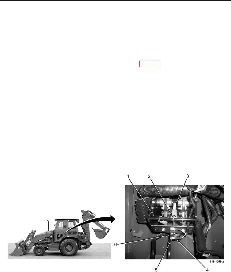
1. Disconnect spring (Figure 1, Item 2) from rod (Figure 1, Item 1).
2. Rotate brake lamp lever (Figure 1, Item 3) away from rod (Figure 1, Item 1).
3. Remove two screws (Figure 1, Item 5) and wires (Figure 1, Item 4) from brake light switch (Figure 1, Item 6).
Figure 1. Brake Light Switch Wires.
0166