
TM 5-2420-231-23-2
0165
REMOVAL CONTINUED
3. Remove two screws (Figure 2, Item 3) and screw (Figure 2, Item 2) from top cover (Figure 2, Item 1) and bot-
tom cover (Figure 2, Item 4). Position top and bottom covers aside.
Figure 2. Cover.
0165
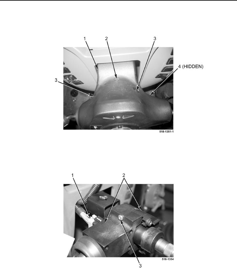
4. Disconnect front console wiring harness (Figure 3, Item 1) from powershift lever (Figure 3, Item 2).
5. Remove two screws (Figure 3, Item 3) and powershift lever (Figure 3, Item 2) from machine.
Figure 3. Turn Signal Switch.
0165
END OF TASK