
TM 5-2420-231-23-2
0174
REMOVAL CONTINUED
2. Remove two bolts (Figure 2, Item 1) and washers (Figure 2, Item 2) from machine.
3. Remove two bolts (Figure 2, Item 3) from machine.
Figure 2. Bolts.
0174
NOTE
Tag and mark wires to aid in installation.
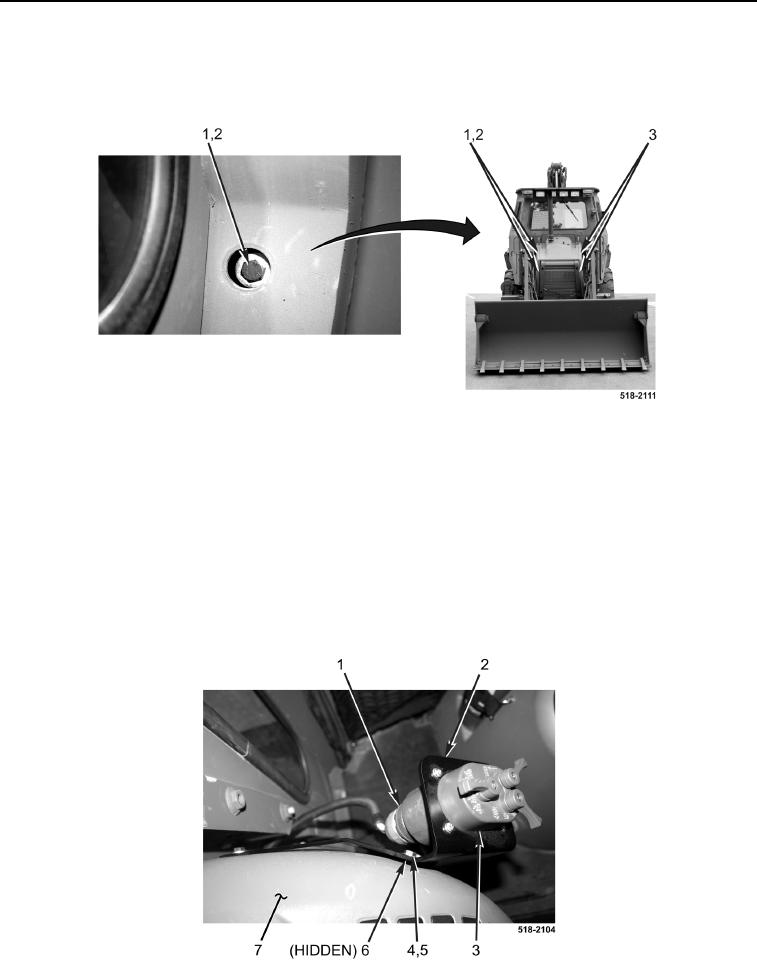
4. Disconnect electrical connector (Figure 3, Item 1) from light control switch controls/indicators
(Figure 3, Item 3).
5. Remove two bolts (Figure 3, Item 4), washers (Figure 3, Item 5), mounting plate (Figure 3, Item 6), light control
switch controls/indicators (Figure 3, Item 3), and bracket (Figure 3, Item 2) from instrument panel
(Figure 3, Item 7).
Figure 3. Light Control Switch Controls/Indicators and Bracket.
0174