• Home
  • Download PDF
  • Order CD-ROM
  • Order in Print
Figure 3. Light Control Switch Controls/Indicators and Bracket.
Figure 6. Front Cover Screws.

Tractor, Wheeled, Industrial Backhoe Loader Nsn 2420-01-532-3399
Page Navigation
  570    571    572    573    574  575  576    577    578    579    580  
img
.
TM 5-2420-231-23-2
0174
REMOVAL CONTINUED
NOTE
Note size and location of cover screws to aid in installation.
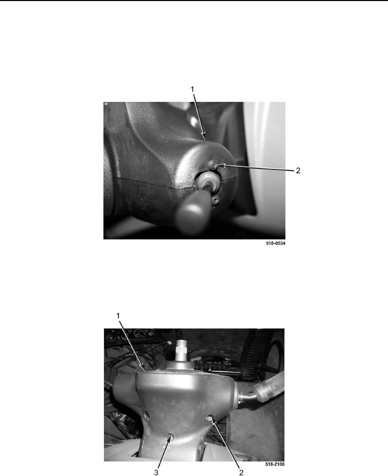
6. Remove two screws (Figure 4, Item 2) from cover assembly (Figure 4, Item 1).
Figure 4. Turn Signal.
0174
7. Remove screw (Figure 5, Item 3) from cover (Figure 5, Item 1).
8. Remove two screws (Figure 5, Item 2) from cover (Figure 5, Item 1).
Figure 5. Top Cover Screws.
0174
0174-3


Privacy Statement
Press Release
Contact

© Copyright Integrated Publishing, Inc.. All Rights Reserved.