
TM 5-2420-231-23-2
0174
REMOVAL CONTINUED
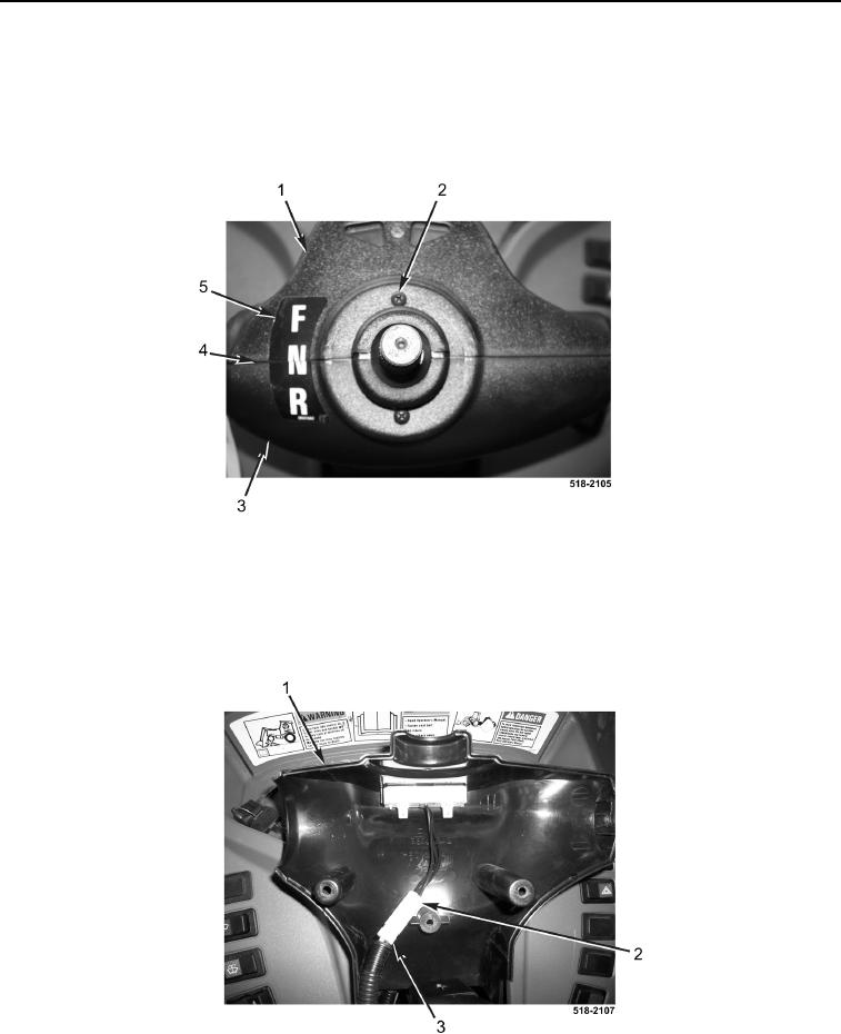
9. Cut decal (Figure 6, Item 5) along seam (Figure 6, Item 4) between upper cover (Figure 6, Item 1) and lower
cover (Figure 5, Item 3).
10. Remove two screws (Figure 6, Item 2) from upper cover (Figure 6, Item 1) and lower cover (Figure 6, Item 3).
11. Remove lower cover (Figure 6, Item 3) from machine.
Figure 6. Front Cover Screws.
0174
12. Disconnect turn signal indicator connector (Figure 7, Item 2) from machine wiring harness connector
(Figure 7, Item 3).
13. Remove upper cover (Figure 7, Item 1) from machine.
Figure 7. Indicator Connector.
0174