
TM 5-2420-231-23-2
0174
REMOVAL CONTINUED
NOTE
Tag and mark wires to aid in installation.
Note location of switches and switch hole covers to aid in installation.
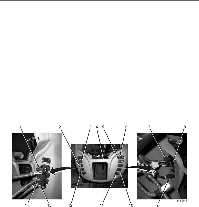
21. Disconnect machine wiring harness connector (Figure 12, Item 1) from front wiper switch (Figure 12, Item 3)
and remove front wiper switch from instrument panel (Figure 12, Item 4).
22. Disconnect machine wiring harness connector (Figure 12, Item 14) from front washer switch (Figure 12,
Item 2) and remove front washer switch from instrument panel (Figure 12, Item 4).
23. Disconnect machine wiring harness connector (Figure 12, Item 13) from front end loader quick-coupler switch
(Figure 12, Item 12) and remove front end loader tool carrier switch from instrument panel (Figure 12, Item 4).
24. Disconnect machine wiring harness connector (Figure 12, Item 7) from front work lamp switch (Figure 12,
Item 6) and remove front work lamp switch from instrument panel (Figure 12, Item 4).
25. Disconnect machine wiring harness connector (Figure 12, Item 8) from flasher lamp switch (Figure 12, Item 5)
and remove flasher lamp switch from instrument panel (Figure 12, Item 4).
26. Disconnect machine wiring harness connector (Figure 12, Item 9) from fuel pump solenoid switch (Figure 12,
Item 11) and remove fuel pump solenoid switch from instrument panel (Figure 12, Item 4).
27. Remove four switch hole covers (Figure 12, Item 10) from instrument panel (Figure 12, Item 4).
28. Remove instrument panel (Figure 12, Item 4) from machine.
Figure 12. Switches.
0174
END OF TASK