
TM 5-2420-231-23-2
0175
INSTALLATION CONTINUED
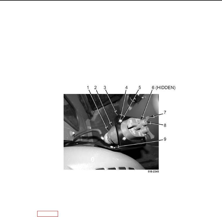
4. Tighten two bolts (Figure 4, Item 9).
5. Install light control switch (Figure 4, Item 2), four washers (Figure 4, Item 4), and screws (Figure 4, Item 5) on
bracket (Figure 4, Item 3).
6. Install three washers (Figure 4, Item 6), knobs (Figure 4, Item 7) and screws (Figure 4, Item 8) on light control
switch (Figure 4, Item 2).
NOTE
Install wires as tagged and marked during removal.
7. Connect connector (Figure 4, Item 1) to light control switch (Figure 4, Item 2).
Figure 4. Light Control Switch.
0175
END OF TASK
FOLLOW-ON TASKS
0175
Connect batteries (WP 0157).
END OF TASK
END OF WORK PACKAGE