
TM 5-2420-231-23-2
0174
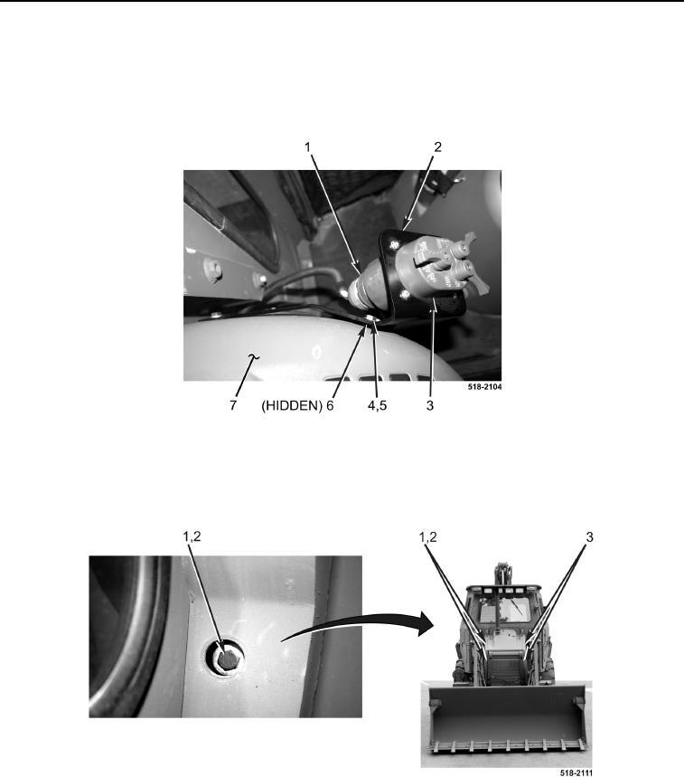
INSTALLATION CONTINUED
25. Install bracket (Figure 22, Item 2), light control switch controls/indicators (Figure 22, Item 3), washers
(Figure 22, Item 5), two bolts (Figure 22, Item 4), and mounting plate (Figure 22, Item 6) on instrument panel
(Figure 22, Item 7).
26. Connect electrical connector (Figure 22, Item 1) to light control switch controls/indicators (Figure 22, Item 3).
Figure 22. Light Control Switch Controls/Indicators and Bracket.
0174
27. Install two bolts (Figure 23, Item 3) on machine.
28. Install two washers (Figure 23, Item 2) and bolts (Figure 23, Item 1) on machine.
Figure 23. Bolts.
0174