
TM 5-2420-231-23-2
0188
REMOVAL CONTINUED
NOTE
Tag and mark wires to aid in installation.
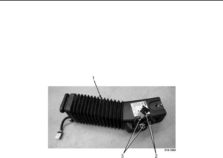
Note routing of tower pilot wiring harness to aid in installation.
2. Disconnect two tower pilot wiring harness connectors (Figure 2, Item 3) from pilot control switches
(Figure 2, Item 2).
3. Position two pilot control switches aside.
4. Remove tower pilot wiring harness (Figure 2, Item 3) from right backhoe control tower boot (Figure 2, Item 1).
Figure 2. Tower Pilot Wiring Harness.
0188
END OF TASK
CLEANING AND INSPECTION
0188
1. Clean and inspect all parts IAW Mechanical General Maintenance Instructions (WP 0369).
2. Clean and inspect all parts IAW Electrical General Maintenance Instructions (WP 0370).
END OF TASK
INSTALLATION
0188
1. Install tower pilot wiring harness (Figure 2, Item 3) on right backhoe control tower boot (Figure 2, Item 1).
2. Position two pilot control switches (Figure 2, Item 2) on right backhoe control tower boot (Figure 2, Item 1).
3. Connect two tower pilot wiring harness connectors (Figure 2, Item 3) to pilot control switches (Figure 2, Item 2).