
TM 5-2420-231-23-2
0195
REMOVAL CONTINUED
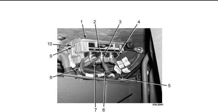
Figure 3. Equalizer.
0195
END OF TASK
CLEANING AND INSPECTION
0195
1. Clean and inspect all parts IAW Mechanical General Maintenance Instructions (WP 0369).
2. Clean and inspect all parts IAW Electrical General Maintenance Instructions (WP 0370).
END OF TASK
INSTALLATION
0195
1. Install equalizer (Figure 3, Item 1), six bolts (Figure 3, Item 9), and nuts (Figure 3, Item 10) on machine.
NOTE
Install wires as tagged and marked during removal.
2. Connect ground cable (Figure 3, Item 8), two 12-V cables (Figure 3, Items 6 and 7), and 24-V cable
(Figure 3, Item 5) on equalizer (Figure 3, Item 1).
3. Install three new lockwashers (Figure 3, Item 2) and nuts (Figure 3, Item 3) on equalizer (Figure 3, Item 1).
4. Position rubber boot (Figure 3, Item 4) over terminal.