
TM 5-2420-231-23-2
0196
REMOVAL CONTINUED
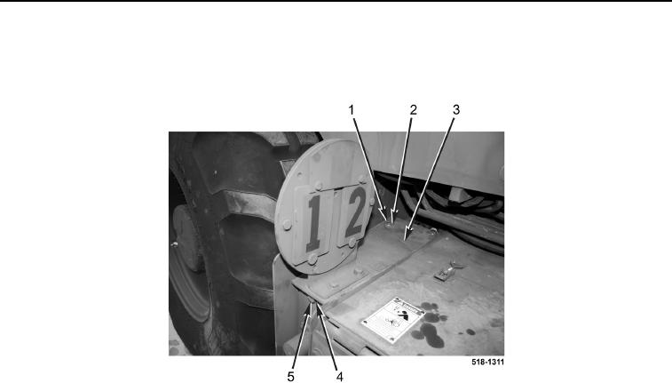
3. Remove two bolts (Figure 2, Item 1) and washers (Figure 2, Item 2) from equalizer cover (Figure 2, Item 3).
4. Remove bolt (Figure 2, Item 5), washer (Figure 2, Item 4), and equalizer cover (Figure 2, Item 3) from machine.
Figure 2. Equalizer Cover.
0196
5. Position two rubber boots (Figure 3, Items 3 and 11) aside.
NOTE
Tag and mark wires to aid in installation.
6. Remove three nuts (Figure 3, Item 6) and lockwashers (Figure 3, Item 5) from equalizer (Figure 3, Item 4).
Discard lockwashers.
7. Remove nut (Figure 3, Item 1) and disconnect four 24-V battery cables (Figure 3, Items 14, 15, 16, and 17)
from junction block (Figure 3, Item 2).
8. Disconnect ground cable (Figure 3, Item 9), two 12-V cables (Figure 3, Items 12 and 13), and 24-V cable
(Figure 3, Item 14) from equalizer (Figure 3, Item 4).
9. Remove 24-V cable (Figure 3, Item 14) from machine.
10. Remove nut (Figure 3, Item 8), and disconnect three ground cables (Figure 3, Item 9) from stud
(Figure 3, Item 7).
11. Remove ground cable (Figure 3, Item 9) from machine.
12. Push 12-V cable (Figure 3, Item 12) through grommet hole (Figure 3, Item 10).