
TM 5-2420-231-23-2
0196
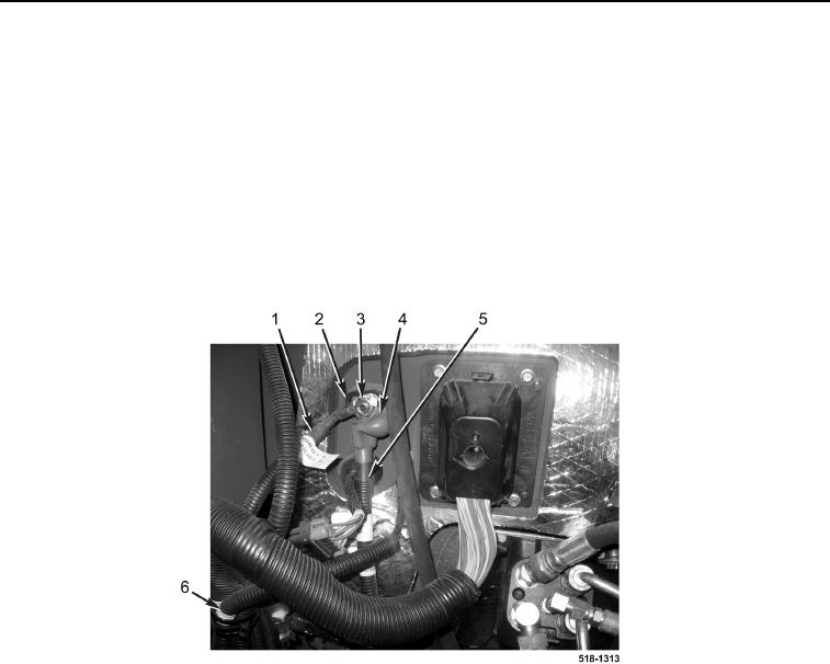
REMOVAL CONTINUED
14. Position boot (Figure 5, Item 4) aside.
15. Remove nut (Figure 5, Item 3), and disconnect two 12-V cables (Figure 5, Items 1 and 5) from junction block
(Figure 5, Item 2).
NOTE
Note location and quantity of tiedown straps to aid in installation.
Note location and routing of 12-V cable to aid in installation.
16. Remove tiedown straps (Figure 5, Item 6) from 12-V cable (Figure 5, Item 5). Discard tiedown straps.
17. Remove 12-V cable (Figure 5, Item 5) from machine.
Figure 5. 12-V Junction Block.
0196
END OF TASK
CLEANING AND INSPECTION
0196
1. Clean and inspect all parts IAW Mechanical General Maintenance Instructions (WP 0369).
2. Clean and inspect all parts IAW Electrical General Maintenance Instructions (WP 0370).
END OF TASK
INSTALLATION
0196
NOTE
Install tiedown straps in location and quantity noted during removal.
1. With assistance, route 12-V cable (Figure 5, Item 5) on machine.
2. Connect two 12-V cables (Figure 5, Items 1 and 5) and install nut (Figure 5, Item 3) on junction block
(Figure 5, Item 2).