
TM 5-2420-231-23-2
0205
LEVEL CHECK CONTINUED
NOTE
The procedure for wheel end oil level check is identical for left-hand and right-hand. Right-
hand wheel end oil level check is shown in this procedure.
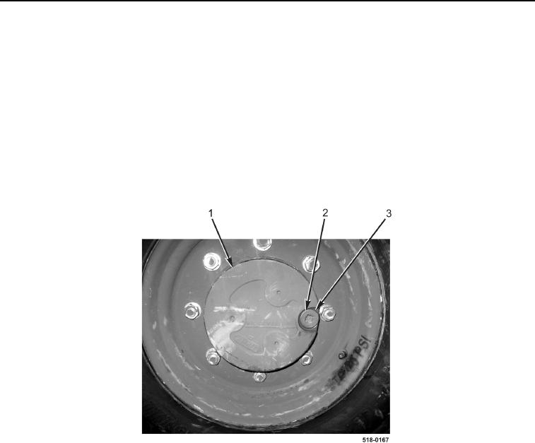
3. Operate machine so that front axle wheel end "oil level" plug (Figure 2, Item 2) is at the 3 o'clock position
(TM 5-2420-231-10).
4. Remove "oil level" plug (Figure 2, Item 2) and O-ring (Figure 2, Item 3) from wheel end (Figure 2, Item 1). Fluid
level should be at the bottom of the hole. Discard O-ring. Add fluid as necessary.
5. Install new O-ring (Figure 2, Item 3) and "oil level" plug (Figure 2, Item 2) on wheel end (Figure 2, Item 1).
6. Repeat steps 3 through 5 for left-hand wheel end oil level check.
Figure 2. Front Axle Wheel End.
0205
END OF TASK