
TM 5-2420-231-23-2
0204
INSTALLATION CONTINUED
WARNING
Use extreme caution when handling heavy parts. Provide adequate support and use
assistance during procedure. Ensure any lifting device used is in good condition and of
suitable load capacity. Keep clear of heavy parts supported only by lifting device. Failure
to follow this warning may result in injury or death to personnel.
NOTE
Front axle weighs 770 lb (349 kg).
Support axle with suitable lifting device and trestles while installing pivot pin.
Install thrust washer in location noted during removal.
It may be necessary to add/remove shims from pivot pin.
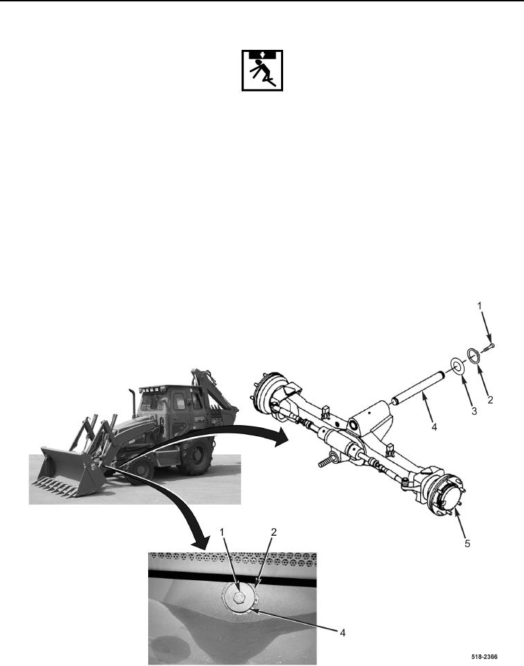
6. Install front axle (Figure 9, Item 5), thrust washer (Figure 9, Item 3), retaining ring (Figure 9, Item 2), and pivot
pin (Figure 9, Item 4) on machine.
7. Install bolt (Figure 9, Item 1) on pivot pin (Figure 9, Item 4).
Figure 9. Front Axle Assembly.
0204