
TM 5-2420-231-23-2
0214
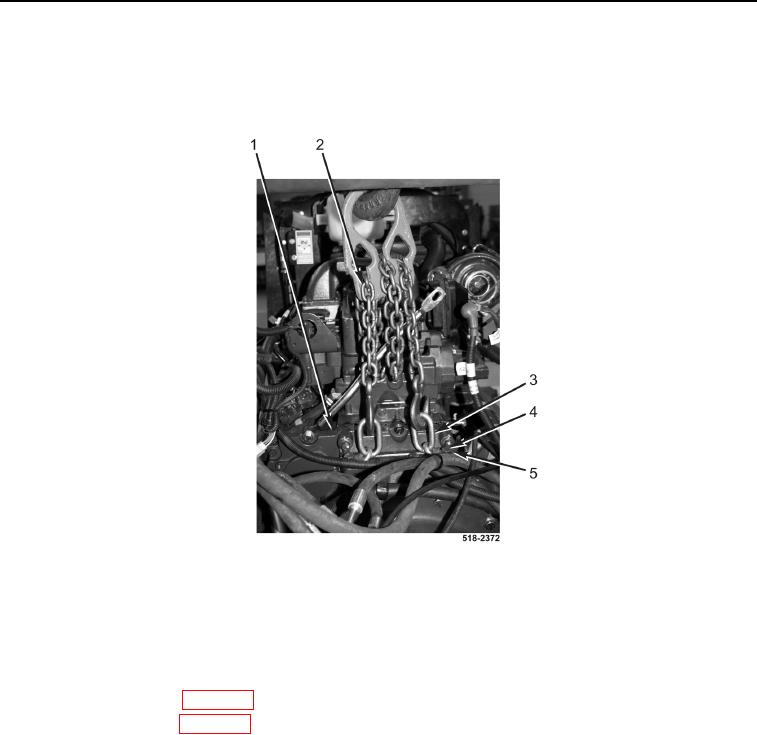
INSTALLATION CONTINUED
8. Remove lifting device and sling (Figure 13, Item 2) from two lifting links (Figure 13, Item 3).
9. Remove two bolts (Figure 13, Item 4), washers (Figure 13, Item 5), and lifting links (Figure 13, Item 3) from
engine (Figure 13, Item 1).
Figure 13. Lifting Equipment.
0214
END OF TASK
FOLLOW-ON TASKS
0214
1. Install cab assembly (WP 0327).
2. Install front drive shaft (WP 0210).
3. Install rear drive shaft (WP 0222).
END OF TASK
END OF WORK PACKAGE
0214-13/(14 blank)