
TM 5-2420-231-23-2
0215
REMOVAL CONTINUED
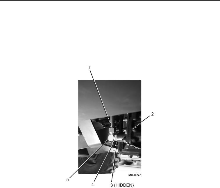
3. Disconnect transmission dipstick tube (Figure 3, Item 1) from fitting (Figure 3, Item 5) and remove dipstick tube
from machine.
NOTE
Note orientation and location of fitting to aid in installation.
4. Loosen nut (Figure 3, Item 4) and remove fitting (Figure 3, Item 5) and O-ring (Figure 3, Item 3) from transmis-
sion (Figure 3, Item 2). Discard O-ring.
Figure 3. Transmission Dipstick Tube.
0215
END OF TASK
CLEANING AND INSPECTION
0215
Clean and inspect all parts IAW Mechanical General Maintenance Instructions (WP 0369).
END OF TASK
INSTALLATION
0215
NOTE
Install fitting as noted during removal.
1. Install new O-ring (Figure 3, Item 3) and fitting (Figure 3, Item 5), on transmission (Figure 3, Item 2).
2. Tighten nut (Figure 3, Item 4) on fitting (Figure 3, Item 5).
3. Connect transmission dipstick tube (Figure 3, Item 1) to fitting (Figure 3, Item 5).