
6
TM 5-2420-231-23-2
FIELD MAINTENANCE
-
FRONT AXLE DRIVE SHAFT REPAIR
0210
Removal, Disassembly, Cleaning and Inspection, Assembly, Installation
INITIAL SETUP
References
Tools and Special Tools
Tool Kit, General Mechanic's
WP 0369
0
0
(WP 0376, Item 117)
WP 0374 (Group Number 0506)
0
Tool Kit, Ball Joint (WP 0376, Item 114)
0
Equipment Conditions
Pliers, Battery Terminal (WP 0376, Item 57)
0
Machine parked (TM 5-2420-231-10)
0
Materials/Parts
Estimated Time to Complete
Rag, Wiping (WP 0375, Item 25)
0
2.0 hr
0
Personnel Required
Two
0
REMOVAL
0210
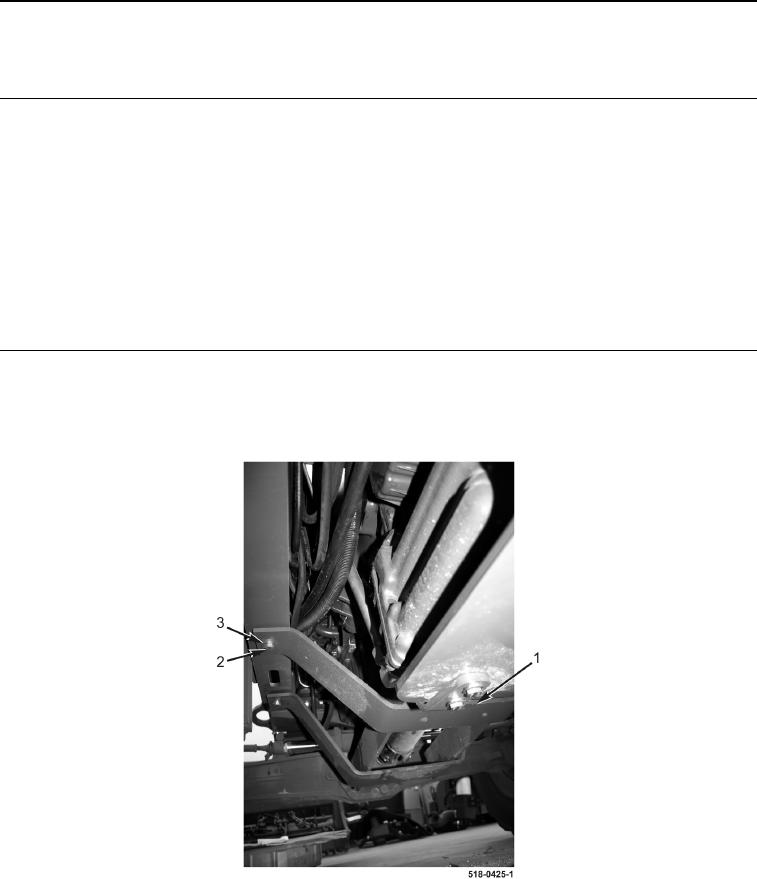
1. With assistance, remove four bolts (Figure 1, Item 2), washers (Figure 1, Item 3), and drive shaft guard
(Figure 1, Item 1) from machine.
Figure 1. Drive Shaft Guard.
0210