
TM 5-2420-231-23-2
0223
ADJUSTMENT
0223
WARNING
Wheels should be blocked prior to releasing parking brake. Failure to follow this warning
may result in injury or death to personnel.
NOTE
The procedure for parking brake light switch adjustment is identical for left-hand and right-
hand parking brake light switches. Right-hand parking brake light switch is shown in this
procedure.
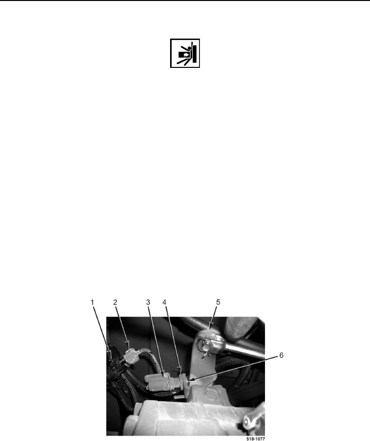
1. Parking brake light switch (Figure 4, Item 3) should close when brake lever (Figure 4, Item 5) is at rest position
when parking brake is released.
2. To adjust parking brake light switch (Figure 4, Item 3):
a. Release parking brake (TM 5-2420-231-10).
b. Disconnect parking brake light switch connector (Figure 4, Item 2) from machine connector
(Figure 4, Item 1).
c.
Loosen jamnut (Figure 4, Item 4).
d. Turn parking brake light switch (Figure 4, Item 3) clockwise in bracket (Figure 4, Item 6) until switch
contacts brake lever (Figure 4, Item 5) and switch opens.
e. Tighten jamnut (Figure 4, Item 4).
f.
Connect parking brake light switch connector (Figure 4, Item 2) to machine connector (Figure 4, Item 1).
g. Apply parking brake (TM 5-2420-231-10).
h. Check for parking brake lights operation.
Figure 4. Switch Adjustment.
0223
END OF TASK