
TM 5-2420-231-23-2
0223
INSTALLATION CONTINUED
NOTE
Install parking brake light switch and jamnut as noted during removal.
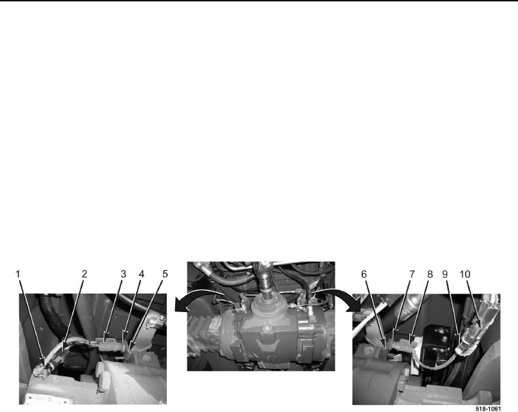
3. Install left parking brake light switch (Figure 3, Item 8) on mounting bracket (Figure 3, Item 6) as noted during
removal.
4. Tighten jamnut (Figure 3, Item 7) on left parking brake light switch (Figure 3, Item 8).
5. Connect left parking brake light switch wiring connector (Figure 3, Item 9) to machine wiring connector
(Figure 3, Item 10).
6. Install right parking brake light switch (Figure 3, Item 3) on mounting bracket (Figure 3, Item 5) as noted during
removal.
7. Tighten jamnut (Figure 3, Item 4) on right parking brake light switch (Figure 3, Item 3).
8. Connect right parking brake light switch wiring connector (Figure 3, Item 1) to machine wiring connector
(Figure 3, Item 2).
Figure 3. Parking Brake Light Switch Wires.
0223
END OF TASK