
6
TM 5-2420-231-23-2
FIELD MAINTENANCE
-
PARKING BRAKE LIGHT SWITCH MAINTENANCE
022
3
Removal, Cleaning and Inspection, Installation, Adjustment
INITIAL SETUP
Equipment Conditions
Tools and Special Tools
Tool Kit, General Mechanic's
Machine parked (TM 5-2420-231-10)
0
0
(WP 0376, Item 117)
Batteries disconnected (WP 0157)
0
References
Estimated Time to Complete
WP 0369
0.5 hr
0
0
WP 0370
0
WP 0374 (Group Number 0602)
0
REMOVAL
0223
NOTE
Note parking brake light switch and jamnut location to aid in installation.
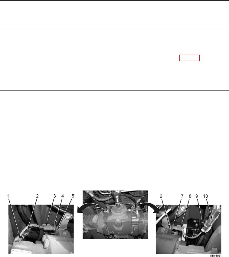
1. Disconnect right parking brake light switch wiring connector (Figure 1, Item 1) from machine wiring connector
(Figure 1, Item 2).
2. Loosen jamnut (Figure 1, Item 4) on right parking brake light switch (Figure 1, Item 3).
3. Remove right parking brake light switch (Figure 1, Item 3) from mounting bracket (Figure 1, Item 5).
4. Disconnect left parking brake light switch wiring connector (Figure 1, Item 9) from machine wiring connector
(Figure 1, Item 10).
5. Loosen jamnut (Figure 1, Item 7) on left parking brake light switch (Figure 1, Item 8).
6. Remove left parking brake light switch (Figure 1, Item 8) from mounting bracket (Figure 1, Item 6).
Figure 1. Parking Brake Light Switch Wires.
0223