
TM 5-2420-231-23-3
0233
LEFT-HAND TUBES INSTALLATION
0233
NOTE
Route loader lift cylinder hydraulic tubes as noted during removal.
Install lines as tagged and marked during removal.
Remove plugs and caps from hoses and fittings.
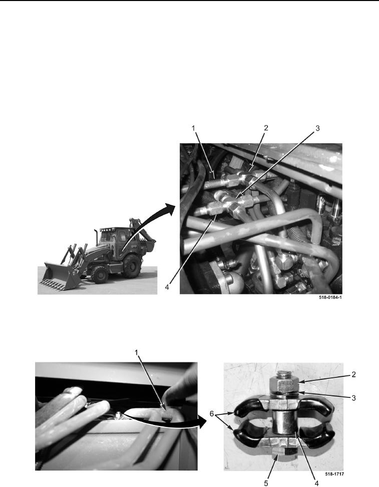
1. With assistance, install two tubes (Figure 13, Items 1 and 4) on machine.
2. Connect tube (Figure 13, Item 4) to fitting (Figure 13, Item 3).
3. Connect tube (Figure 13, Item 1) to fitting (Figure 13, Item 2).
Figure 13. Tubes (Left-Hand).
0233
4. Install spacer (Figure 14, Item 4), two brackets (Figure 14, Item 6), new lockwasher (Figure 14, Item 3), bolt
(Figure 14, Item 5), and nut (Figure 14, Item 2) on two tubes (Figure 14, Item 1).
Figure 14. Rear Bracket (Left-Hand).
0233